
Front Panel
The System 00 front panel reproduces the large operator control panel described in the 1971 System 00 manual. Where the FRED I front panel is limited to a few switches, this panel gives full manual control of the CPU: programs can be entered from the hex keypad, memory can be examined and modified, and registers can be set and inspected. See the picture on the right for the Emma 02 version.
The procedures for using the panel are described in the Operating Procedures section.
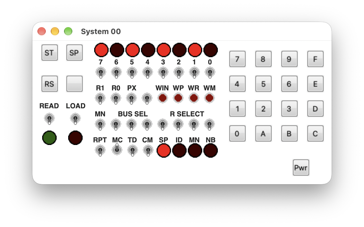
LEDs
- Bit LEDs 7 to 0: eight LEDs showing the byte on the bus selected with the Bus Select switches. While a program is entered on the hex keypad, they display the 8 bits of each byte entered.
- Run LED: on while the CPU is executing; off when the CPU is in the idle state or the clock is stopped.
- Error LED: on when a cassette parity error occurs.
- SP LED: on when the time pulses (the clock) are stopped.
- ID LED: on when the CPU is in the idle state.
- MN LED: on when manual operation is enabled with the MN switch.
- NB LED: on when the panel is ready for the next input byte. It turns off after the first digit of a digit pair is entered and back on when the completed byte is stored.
Clock control
- ST push button: starts the time pulses. The SP LED turns off and execution resumes from where it stopped.
- SP push button: stops the time pulses at the end of the current machine cycle; the SP LED turns on.
- RS push button: resumes execution from the idle state: the idle instruction is terminated and the instruction at the next address is fetched and executed. With the READ switch on, RS instead displays the memory byte at the current address on the bit LEDs and increments the address.
- CL push button (unlabelled on the emulated panel, directly below SP): clears the CPU to the idle state. All I/O devices are deactivated, the time pulses are stopped, and the P, N, and R(0) registers are cleared. The ID and SP LEDs turn on.
Loading and reading
- LOAD switch: arms the hex keypad for direct loading. After CL, each completed digit pair is stored in memory sequentially, starting at address 0000 (hexadecimal). The NB LED indicates when the panel is ready for the next byte.
- READ switch: with READ on, the bit LEDs display the memory byte at the current address, and RS steps to the next address.
Hex keypad
The sixteen keys enter bytes in direct load mode: enter the least significant digit first, followed by the most significant digit. The byte is stored when the second digit is entered. For example, press 7 followed by 8 to store the byte 87 (hexadecimal).
Manual operation
The switches and push buttons below operate directly on the CPU registers and memory. They are only meaningful when the MN (manual) switch is on, which also turns the MN LED on.
-
0-7 switches: eight switches that set the byte on the bus. With the Bus Select switches set to
000, the bit LEDs display the switch settings. - R Select switches: four switches that select the register R(0) to R(F) for the WR push button, as a 4-bit binary value.
- R1 and R0 switches: control which byte of the selected register the WR push button writes. Each switch inhibits the opposite byte: R1 up inhibits the low byte and R0 up inhibits the high byte.
- PX switch: sets both P and X to 7, so that R(7) serves as both the program counter and the data pointer.
- WIN push button: loads the byte set on the 0-7 switches into the I and N registers.
- WP push button: loads the byte into the P register.
- WR push button: writes the byte into the selected byte or bytes of the selected register. The selected register is also copied into the address register, so it can be displayed with the Bus Select switches.
- WM push button: writes the byte into memory at the address in the address register.
The byte written by WR depends on the R1 and R0 switches as follows:
| R1 | R0 | WR writes |
|---|---|---|
| down | down | both bytes |
| up | down | high byte only |
| down | up | low byte only |
| up | up | nothing |
Bus Select
The three Bus Select switches select the byte displayed on the bit LEDs. The settings below are given as the three switch positions from left to right on the panel:
| Setting | Display |
|---|---|
000 |
The 0-7 switch settings (when MN is on) |
001 |
The memory byte at the address register |
010 |
The low byte of the address register |
011 |
The T register |
100 |
The high byte of the address register |
101 |
The N register |
110 |
The D register |
111 |
A fixed test pattern (00100001) for checking the bit LEDs |
Cycle control
- RPT switch: repeats the current machine cycle continuously while on.
- MC switch: executes exactly one machine cycle each time ST is pressed, for single-stepping.
- CM switch: clears memory when used together with RPT, as described in the Operating Procedures section.
Power
- Pwr push button: turns the System 00 power off.
Note: The TD switch and the unmarked switch next to PX are not supported in the Emma 02 System 00 emulator; their functions are not documented in the surviving material. The punched card reader of the original system is not emulated either; programs are entered with the hex keypad or loaded from the host computer.