F&M EPROM Switchboard
This card was not developed by COMX but was a home made extension by F&M, we only made one!
The EPROM Switchboard includes one 2 KB EPROM with the firmware and up to five 8 KB EPROMs with additional software. The 2 KB firmware ROM is placed at address @F800 - @FFFF, this location is also used by the CDP 1870 but the CDP 1870 in the COMX architecture did not allow reading of page memory so selecting an EPROM at this location was actually possible. The 8 KB EPROMs are all mapped at address @C000 - @DFFF.
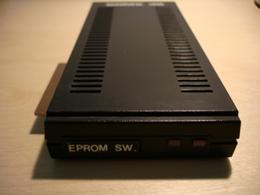
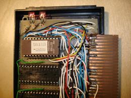
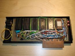
We managed to fit the home made card into an original COMX housing, as shown in the picture to the right, making it look quite nice. That is as long as you didn’t open the box. In the pictures below you can see the card still has the 2 KB firmware EPROM which is now included in the latest emulator release. None of the remaining EPROMs were left in the box, my guess is that we re-used them for other projects. Still I managed to create some EPROM files with software similar to how we had it running at the time.
The firmware has commands to switch between the 8 KB EPROMs (CARDSx y), as only one can be active at any one time, to show all SW (CARDSx CAT, see screenshot below) and to execute or load the SW stored in the EPROMs (CARDSx “software”). Details of commands is explained in the emulator help pages.
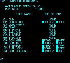
Additional EPROM files now include:
- F&M Utilities including: OLD (recover BASIC after reset), F&M Clock, Char (small character shape), Turbo cassette loader, F&M Disk routines (Init, Lock, Unlock) and a DOS boot loader loadable from EPROM instead of disk.
- Disk Utilities: COMX Init, Lock, Unlock, Diskcopy, Filecopy, Diskhelp
- F&M Monitor both in English and Dutch
- F&M Basic 2.0
- Tennismania (pong game)
- Hit and Run (COMX game)
In principle any software < 8 KB can be put in an EPROM file to work with the emulator. The firmware includes functionality to copy BASIC software into RAM and set BASIC parameters correctly, copy assembly routines to any RAM memory location or RUN software directly from the EPROM in location @C000-@DFFF.
EPROMs or EPROM files are build up as follows:
@C000 00
@C001 20 - F&M Switchboard indicator
@C002 08 - EPROM size
@C010 C0 F8 00 - Branch to firmare
@C020-@C02F - Name (ending with 0D)
@C030-@C031 - Execution address
@C032 - Type, where 0 is software running in EPROM address range, 1 assembly code to be copied to RAM, 2 BASIC program to be copied to RAM.
@C033-@C034 - Memory start location of software (used for copy to RAM)
@C035-@C036 - Destination address in RAM (used for copy to RAM)
@C037-@C038 - Memory end location of software (used for copy to RAM)
@C039 - High byte of DEFUS value (used for copy of BASIC program)
@C03A-@C03B - RAM start location that software will use (shown in CAT)
@C03C-@C03D - RAM end location that software will use (shown in CAT)
Note @C020-@C03F should be repeated for every program, so info for program 2 can start at @C040, 3 at @C060 etc. If no more programs are included a 0 is needed at @C0x0. So when the EPROM has only 1 program @C040 has to be 0.
To switch to a different 8K EPROM in assembly the OUT 1 instruction can be used. Bit 5, 6 and 7 are used for the EPROM selection (bit 1 to 4 were used for the expansion box slot selection and bit 5 and 6 are also used for the RAM card, see also I/O Map)
Firmware Commands
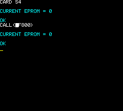
CARD Sx or CALL(@F800)
The 'CARDS Sx' command (or when no expansion box is used 'CALL(@F800)' will select the EPROM Switchboard and show which of the 5 EPROMs is active.
For example when the EPROM Switchboard is defined in expansion box slot 4:
CARD S4
will result in:
CURRENT EPROM = x
where 'x' is EPROM number 0 to 4. Example on the right is showing both CARD S4 and CALL(@F800)
CARD Sx y or CALL(@F800) y
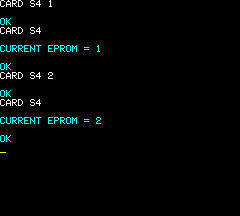
The 'CARDS Sx y' command (or when no expansion box is used 'CALL(@F800) y' will select the EPROM Switchboard and EPROM y, where y is 0 to 4.
For example when the EPROM Switchboard is defined in expansion box slot 2:
CARD S4 4
will result in selection of EPROM 4 between address hex C000-DFFF. Example on the left is showing the selection of EPROM 1 followed by EPROM 2
CARD Sx CAT or CALL(@F800) CAT
The 'CARDS Sx CAT' command (or when no expansion box is used 'CALL(@F800) CAT' will select the EPROM Switchboard and show all software defined in the firmware EPROM as well as in EPROM 0 to 4.
For example when the EPROM Switchboard is defined in expansion box slot 2:
CARD S4 CAT
will show something like:
F&M EPROM SWITCHBOARD

   AVAILABLE EPROM'S: x, y, z...
   ROM SIZE        : size K

    FILE NAME        USE OF RAM

  01:OLD                NONE
  02:CLOCK-ON       @BFF0 / @BFF4
  03:CHAR               NONE
  04:F&M INIT       @B000 / @B5FF
  05:STARTUP        @4400 / @479F
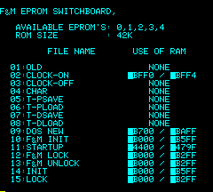
Where 'x, y, z...' indicates which EPROM numbers are used/defined (0, 1, 2, 3 and/or 4), 'size' is the total size of all EPROMs (10K to 42K). In the above example 5 programs are loaded in the EPROMs, where 'OLD' and 'CHAR' indicate 'NONE' meaning no RAM is used when executing these programs, in other words they RUN in EPROM memory. In the other cases the addresses of the used RAM is indicated. Any software that indicates use of RAM from hex 4400 like 'STARTUP' above will be copied to RAM and overwrite any BASIC software in COMX memory.
CARD Sx "software" or CALL(@F800) "software"
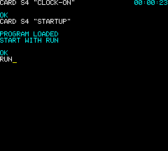
The 'CARDS Sx "software"' command (or when no expansion box is used 'CALL(@F800) "software"' will select the EPROM Switchboard and execute or load indicated software if available.
For example when the EPROM Switchboard is defined in expansion box slot 2, the followin will start the 'CLOCK-ON' software:
CARD S4,"CLOCK-ON"
However:
CARD S4,"STARTUP"
will load the program STARTUP in BASIC memory (overwriting all other BASIC software in COMX memory). And the following message is shown:
PROGRAM LOADED
START WITH RUN
Note that in some cases the "software" should be followed by a number (CHAR) or a '+' (LOAD/SAVE routines) see also software format described below.
EPROM 0 Software: F&M Utilities
OLD
Format: CARD Sx "OLD"
F&M Old, this small program recovers a BASIC program after a computer reset, giving the COMX BASIC a 'warm' start. Note this only works if the BASIC program in memory before the restart started with:
10 REM
CLOCK-ON, CLOCK-OFF
Formats:
CARD Sx "CLOCK-ON"
CARD Sx "CLOCK-OFF"
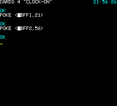
F&M Clock: CLOCK-ON will start a clock in the top right of the screen, CLOCK-OFF will turn it off. The remaining clock functions can be done by POKE commands:
POKE (@BFF0,0): Clock printed
POKE (@BFF0,1): Not printed but running
POKE (@BFF1,h): Set hours
POKE (@BFF2,m): Set minutes
POKE (@BFF3,s): Set seconds
When the BASIC scroll function is used the clock will still be printed on the top right, however note that sometimes (quite often when NOT using the f&m expansion rom) the clock will not be removed and the 'old' time will show up at the bottom of the screen. I'm not sure if this is a fault in the original clock software or a bug in the emulator.
CHAR
Format: CARD Sx "CHAR" y
F&M Char, will 'SHAPE' (define) small character set:
y = 1: Default COMX characters
y = 2: Small under shift
y = 3: Capitals under shift
T-PSAVE, T-PLOAD, T-DSAVE, T-DLOAD and + variants
Formats:
CARD Sx "T-PSAVE"
CARD Sx "T-PLOAD"
CARD Sx "T-DSAVE"
CARD Sx "T-DLOAD"
CARD Sx "T-PSAVE"+
CARD Sx "T-PLOAD"+
CARD Sx "T-DSAVE"+
CARD Sx "T-DLOAD"+
F&M Turbo tape routines work exactly like BASIC save/load commands except much faster. The '+' versions are improved versions resulting in different wav formats. The wav files created with the regular versions can be loaded with the regular and '+' versions. Wav files created with the '+' versions are not loadable with the regular versions.
DOS NEW
Format: CARD Sx "DOS NEW"
This more or less performs the same as 'DOS NEW' except this loads the DOS boot loaders from EPROM instead of from DISK. Normally not used directly, but this program is called before running any of the other EPROM disk routines to allow starting them without a formatted disk present.
F&M INIT
Format: CARD Sx "F&M INIT"
Formats a disk like the INIT program however with an F&M boot sector which will attempt to load and run a program called 'STARTUP' when DOS is initialised (like with DOS NEW).
STARTUP
Format: CARD Sx "STARTUP"
An example start-up program showing all programs on disk and allowing starting them from a menu. This software can be saved on a disk created by F&M INIT and will in that case start automatically after the first 'DOS' command. To save STARTUP to disk use the following DOS command:
DOS SAVE,"STARTUP",@4400
F&M LOCK
Format: CARD Sx "F&M LOCK"
Locks all software on the disk.
F&M UNLOCK
Format: CARD Sx "F&M UNLOCK"
Unlocks all software on the disk.
EPROM 1 Software: Disk Utilities
INIT
Format: CARD Sx "INIT"
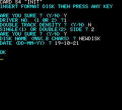
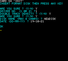
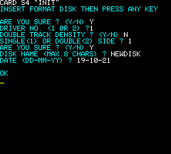
COMX Disk initialisation program to create a new disk image including COMX DOS boot data. See examples for 3 different disk options below.
LOCK
Format: CARD Sx "LOCK"
COMX lock software to lock one file on a disk.
UNLOCK
Format: CARD Sx "UNLOCK"
COMX unlock software, to unlock one file on a disk.
DISKCOPY
Format: CARD Sx "DISKCOPY"
COMX disk copy software to make an exact copy of a disk, including a format (initialisation) of the destination disk before copy begins.
FILECOPY
Format: CARD Sx "FILECOPY"
COMX file copy software to copy any file to another disk image.
DISKHELP
Format: CARD Sx "DISKHELP"
COMX disk help program, showing the description of disk error codes.
EPROM 2 Software: F&M Monitor
Format: CARD Sx "MONITOR"
F&M Monitor+, standard ‘monitor’ program to write machine code software (using hex code) and to inspect memory. The program also includes some simple tools for moving code, register inspection and clearing memory. One very handy feature is the ability to insert ‘NOP’ (or #C4) instructions anywhere in the written code and at the same time ‘translating’ 1802 branch instructions, i.e. changing the destination address if changed by the ‘insert’. This includes additional ‘inserts’ if a short branch has to be changed to a long branch and as such needed 3 bytes instead of 2; also the branch itself will in such cases be changed to a long branch.
EPROM 3 Software: F&M Basic
Format: CARD Sx "F&M BASIC"
F&M BASIC loaded from EPROM to COMX RAM.
EPROM 4 Software: Tennismania
Format: CARD Sx "TENNISMANIA"
Pong clone for the COMX, written by Steven de Vries and F&M.
Additional EPROM Software: Hit and Run
Format: CARD Sx "HIT AND RUN"
COMX Game Hit and Run. This EPROM is not selected by default but can be loaded instead of EPROM 1 to 4.

