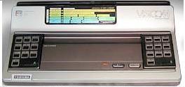
Video
The Visicom COM-100 uses the CDP 1861 for video output. For details on the CDP 1861 please see the data sheets for this chip or the 'summary' on the CDP 1861 page. The Visicom controls the CDP 1861 via OUT 1 to switch the display on and EF1 to indicate the display status. I don't know if any INP/OUT is implemented to switch the display off.
The Visicom firmware and games use the most common CDP 1861 resolution of 64 x 32 with interrupt routine entry point at @02B1 and display memory at both @1100-@11FF and @1300-@13FF.
I'm not 100% sure how the 2 display memory areas are used in combination with the additional video HW (possibly 2 TC4021 8-bit shift registers). My best guess is the following: area @1100-@11FF defines colour bit 0 and @1300-@13FF bit 1. These 2 bits define which colour is used for that specific pixel out of the 64 x 32 resolution. Colour definition:
- Dark green (background)
- Blue
- Green
- Red
Again I'm not sure how the 2 bits are read by the HW using the CDP 1861 DMA and interrupt functions. The above works for the build in games in the emulator.
The display status is an active low output signal occurring for a period of four horizontal cycles prior to the beginning and end of the 128 line display window. The signal is used by the firmware interrupt routine to indicate the last 'row' of the display area.

