Front Panels
Main Panel
The Netronics Elf II front panel includes the IN button, hex buttons, Q LED and TIL displays.
IN (yellow elippse): This button initiates a DMA IN operation of the processor. The values of the two previously pushed hex buttons (highlighted in green) will be written into the memory pointed to by R[0] when the computer is in load mode.
LOAD (highlighted in orange): When this switch is up and RUN (highlighted in red) is down the computer is set into load mode. In this mode, values can be set by pushing hex buttons (highlighted in green) and then loaded into memory by pressing the IN button (highlighted in yellow). After the transfer, the data displays (highlighted in black) will show the byte written and R[0] will be stepped up with 1.
MP (highlighted in blue): This switch when up disables memory write. This will allow you to step through memory in the LOAD mode without actually modifying memory, with each IN (highlighted in yellow) press, but would still increment the address. Using this you can step to an address in memory, turn MP off and then write a new value into memory.
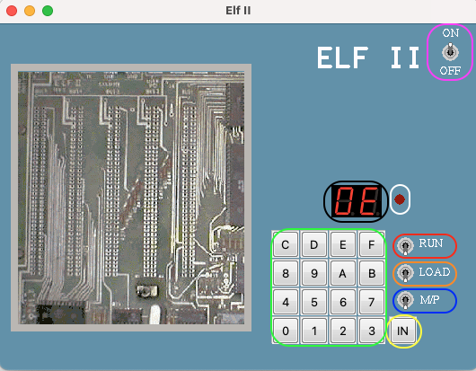
RUN (highlighted in red): When this switch is up and LOAD (highlighted in orange) is down the CPU is set into run mode and a program will begin to execute from address 0. When both RUN and LOAD are down, the CPU is put into the reset state, setting the current address back to 0, and disabling DMA and INT operations.
ON/OFF (highlighted in purple): Turning this switch down will end the Netronics Elf II emulator.
Q (highlighted in white): Shows status of the CPU Q flag.