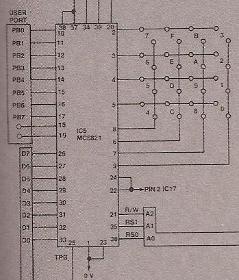
Keyboard
The I/O port PA of the PIA MC6821 is used in conjunction with the keyboard. This is divided into a 4 x 4 matrix with a normally open contact at each cross point. PA0 to PA3 (pin 2 to 5) connect to the 'rows' of the matrix, while PA4 to PA7 (pin 6 to 9) connect to the 'columns' of the matrix. Internally these eight lines have pull-up resistors, and when used as input are normally high when open.
The 'row' lines (PA0 to PA3) are made output lines and are programmed in software to be logic 0. This is done by writing #0F to the data direction register (bit 0-3 are 1 = output, bit 4 to 7 are 0 = input). The ETI writes the data direction register as follows:
- First the data direction register needs to be selected, this is done setting bit 2 of the control register to 1 (by an OUT 2 with data bit 2 = 1 and address lines bit 0 = 1 and bit 1 = 0).
- Second to write #0F to the data direction register (by an OUT 2 with address lines bit 0 and bit 1 equal to 0).
Pressing any key will join a row line (low) to a column line (high), pulling the column line (an input) low. The software (monitor program) detects this and changes the function of the rows and columns over to find the key depressed. Some short delay is normally included to 'debounce' the key contacts. Software is used to determine the 'value' of the key depressed.
The ETI writes the PA output part as follows:
- First the peripheral register needs to be selected, this is done setting bit 2 of the control register to 0 (by an OUT 2 with data bit 2 = 0 and address lines bit 0 = 1 and bit 1 = 0).
- Second to write the desired output (by an OUT 2 with address lines bit 0 and bit 1 equal to 0).
The ETI reads the PA input part as follows:
- First the peripheral register needs to be selected, this is done setting bit 2 of the control register to 0 (by an OUT 2 with data bit 2 = 0 and address lines bit 0 = 1 and bit 1 = 0).
- Second to read the desired input (by an OUT 2 with address lines bit 0 and bit 1 equal to 0).

