Front Panels
Main Panel
The Cosmac Elf front panel includes the IN button, switches, Q LED and TIL displays, see picture on the right for the Emma 02 version.
IN (highlighted in yellow): This button initiates a DMA IN operation of the processor. The values of the 8 data switches (highlighted in green) will be written into the memory location in R[0] when the computer is in load mode.
LOAD (highlighted in orange): When this switch is up and RUN (highlighted in red) is down the computer is set into load mode. In this mode, values can be set on the 8 data switches (highlighted in green) and then loaded into memory by pressing the IN button (highlighted in yellow). After the transfer, the address displays (highlighted in grey) will show the address just written and the data displays (highlighted in black) will show the byte written.
MP (highlighted in blue): This switch when up disables memory write. This will allow you to step through memory in the LOAD mode without actually modifying memory, with each IN (highlighted in yellow) press, but would still increment the address. Using this you can step to an address in memory, turn MP off and then write a new value into memory.
RUN (highlighted in red): When this switch is up and LOAD (highlighted in orange) is down the CPU is set into run mode and a program will begin to execute from address 0. When both RUN and LOAD are down, the CPU is put into the reset state, setting the current address back to 0, and disabling DMA and INT operations.
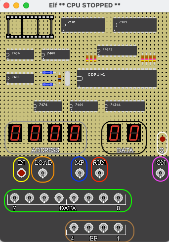
ON (highlighted in purple): Turning this switch up will end the Cosmac Elf emulator.
DATA (highlighted in green): These 8 switches are used to specify a byte to be input to memory. During RUN mode, reading port 4 will read the value of these switches.
EF (highlighted in brown): These 4 switches are connected to the 4 EF inputs of the CPU.
Q (highlighted in white): Shows status of the CPU Q flag.
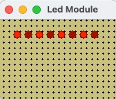
LED Module
The Led Module includes 8 LEDs, which will show the binary value of the OUT 4 instruction. In the picture on the left, value hex AA is shown.
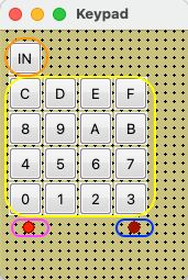
HEX Keypad
The HEX Keypad includes 16 HEX buttons, an IN button and 2 LEDs.
In load mode, specify a hex value by clicking two hex buttons (yellow ellipse). After this click the IN button (highlighted in orange) and the specified value will be written into the memory location in R[0]. When the left LED (highlighted in purple) is on the first nibble can be specified and when the right LED (highlighted in blue) is on the second nibble can be specified.