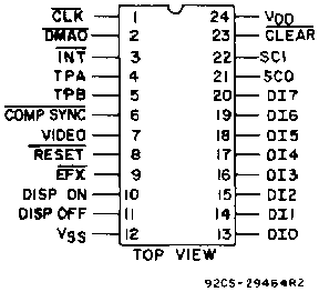
CDP 1861: Video Display Controller
This page includes part of (and for me) the most interesting information from the CDP 1861 data sheet.
Features
- Supports bit-mapped video display tor graphic flexibility
- Generates composite horizontal and vertical sync
- Programmable vertical resolution for matrix display of up to 64 x 128 segments
- Real-time interrupt generator
- Clear input
- External display control
Application Information
The CDP 1861 uses both the interrupt and direct memory access (DMA) output channel of the microprocessor for display refresh. The microprocessor specifies the area of memory displayed via the interrupt routines, and the DMA output channel is the mechanism which transfers the data from memory to the CDP 1861 via the 8-bit data bus. The data are then shifted out one bit at a time at the clock frequency to generate the video signal.
The display is a bit map of memory. Each bit in the display memory corresponds to one spot on the video screen. Logical 1 bit in memory correspond to white or lighted spots in the display. The highest resolution that may be produced is 128 vertical by 64 horizontal segments. This resolution requires 1024 bytes of memory for the display. The upper left-most spot that can be displayed on the video screen is the most significant bit of the first byte in the display refresh memory buffer. The starting location of the display buffer is initialized in the interrupt routine and may be anywhere in addressable memory (ROM, RAM, or both). The lower right-most spot that can be displayed is the least significant bit of the last byte of the display bit map. For each of the 128 horizontal display lines, 8 bytes of memory are sequentially accessed and displayed from left to right on the video screen. Adjacent illuminated spots appear contiguous both in the horizontal and in the vertical directions. All display manipulations are accomplished by changing the data within the display buffer or by changing display buffers.
The CDP 1800 series microprocessor must be in synchronization with the CDP 1861 during the display window. Exactly six machine cycles must be executed beyond the eight DMA cycles during each line, and an even number of cycles (262 x 14) must be executed from the start of one display window to the start of the next. These requirements insure that the DMA burst will not be delayed one cycle waiting for an instruction to finish - this delay would cause jitter on the screen. These requirements can be accomplished in two steps: 1. the main program must not execute any 3-cycle instructions (i.e., SKIP, LONG BRANCHES, and NOP), and 2. the interrupt routine, including the interrupt cycle itself, must employ an even number of cycles, and must be synchronized with the DMA bursts. There must be 29 cycles between the interrupt cycle and the first burst of eight DMA cycles. This timing is accomplished by executing an early 3-cycle instruction to compensate for the interrupt cycle. Furthermore, exactly three 2-cycle instructions must be executed between each sucessive burst. Occasionally these restrictions may be ignored at the expense of jitter on the screen.
For the 128 x64 display, the CDP 1800 series microprocessor software requirement is straightforward. The DISP STATUS/EF1 line is not required, and EF1 may be used for other purposes. A simple interrupt routine merely resets the DMA pointer, R0, to the beginning of the display buffer area (see fig 1) - note the 3-cycle NOP instruction at the beginning which compensates for the 1-cycle interrupt. The first burst of eight DMA cycles occurs just as this routine finishes, as indicated by the bracket following the RETURN instruction (70). Exactly 29 cycles separate the interrupt request cycle and the first DMA burst. The interrupt routine must last at least 28 cycles, because the interrupt request line is held up that long by the CDP 1861.
Machine Code |
|
Assembly Language |
Comments |
72 |
INTRET |
: LDXA |
. . RESTORE D |
70] |
|
RET |
. . RETURN |
C4 |
INT |
: NOP |
. . ENTRY POINT |
22 |
|
DEC R2 |
. . R2 = STACK PTR |
78 |
|
SAV |
. . T->STACK |
22 |
|
DEC R2 |
|
52 |
|
STR R2 |
. . D->STACK |
E2, E2 |
|
SEX R2; SEX R2 |
. . NOP |
F8 xx B0 |
|
A.1 (DISMEM)->RO.I |
. . LOAD RO WITH |
F8 yy A0 |
|
A.0 (DISMEM)->RO.O |
. . START ADDR OF DISP. MEM. |
30 INTRET |
|
BR INTRET |
. . BRANCH TO INTERRUPT RETURN |
Fig 1. Interrupt routine tor 64 x 126
When less RAM is to be used (less resolution), a more complicated interrupt routine is used. The interrupt routine is protracted for the full duration of the display window, and the six free cycles in each line are used to execute three instructions, which maintain control over the DMA pointer, RO.1. In the simplest cases, each line of 8 bytes is repeated n times to give 128/n vertical resolution. With n = 4, for example, 64 x 32 resolution is obtained. Such an interrupt routine is shown in Fig. 2. The use of three instructions per line does not leave time to control a loop, so each of four copies of the line corresponds to three instructions in the main loop, starting at EFX. The EFX signal, applied to EF1, is used to signal the last pass through the loop.
Machine Code |
|
Assembly Language |
Comments |
72 |
INTRET |
: LDXA |
. . RESTORE D |
70 |
|
RET |
. . RETURN |
C4 |
INT |
: NOP |
. . 3 CYC. INSTRU. USED |
|
|
|
. . FOR PGM. SYNC |
22 |
|
DEC R2 |
. . R2 = STACK PTR |
78 |
|
SAV |
. . T->STACK |
22 |
|
DEC R2 |
|
52 |
|
STR R2 |
. . D->STACK |
F8 xx B0 |
|
A1 (DISMEM)->RO.I |
. . LOAD RO WITH |
F8 yy A0 |
|
A.0 (DISMEM)->RO.O |
. . START ADDR. OF DISP. MEM |
C4, C4 |
|
NOP; NOP |
. . NOPS USED FOR SYNC |
E2 |
DISP |
: SEX2 |
|
80] |
|
GLO RO |
. . LINE START ADDR.->D |
E2 |
|
SEX2 |
. . NOP |
20 |
|
DEC RO |
. . RESET RO.1 IF PASS PG |
AO] |
|
PLO RO |
. . LINE START ADDR.->RO.0 |
E2 |
|
SEX2 |
. . NOP |
20 |
|
DEC RO |
. . RESET RO.1 IF PASS PG |
AO] |
|
PLO RO |
. . LINE START ADDR.->RO.0 |
E2 |
|
SEX2 |
. . NOP |
20 |
|
DEC RO |
. . RESET RO.1 IF PASS PG |
AO] |
|
PLO RO |
. . REPEATS SAME LINE |
3C DISP |
|
BN1 DISP |
. . LOOPS 32 TIMES |
30 INTRET |
|
BR INTRET |
. . END OF DIPLAY |
Fig 2. Interrupt routine tor 64 x 32 format
For other values of n, similar routines can be devised. For n = 2, the 64 x 64 format, the last 4 lines need special treatment (see Fig. 3). Other schemes are possible, resulting in other resolutions which vary on command from the main program, or even resolutions which vary through the display window.
Machine Code |
|
Assembly Language |
Comments |
72 |
INTRET |
: LDXA |
. . RESTORE D |
70 |
|
RET |
. . RETURN |
C4 |
INT |
: NOP |
. . 3 CYC. INSTR. FOR PGM. SYNC |
22 |
|
DEC R2 |
. . R2 IS STACK PTR |
78 |
|
SAV |
. . T-STACK |
22 |
|
DEC R2 |
|
52 |
|
STR R2 |
. . D-STACK |
F8 xx B0 |
|
A.1 (DISMEM)->RO.I |
. . DISMEM IS START ADDR |
F8 yy A0 |
|
A.0 (DISMEM)->RO.O |
. . OF DISPLAY MEMORY |
C4, C4 |
|
NOP; NOP |
. . NOPS FOR PGM SYNC |
E2 |
|
SEX2 |
|
80] |
DISP |
: GLO RO |
. . NEW LINE |
E2 |
|
SEX2 |
. . NOP |
20 |
|
DEC RO |
. . RESTORES RO.1 IF PASS PG |
AO] |
|
PLO RO |
. . REPEATS SAME LINE |
E2 |
|
SEX2 |
. . NOP |
3C DISP |
|
BN1 DISP |
. . LOOP 60 TIMES |
80] |
DISEF |
: GLO RO |
. . LAST 4 VIDEO LINES |
E2 |
|
SEX2 |
. . NOP |
20 AO] |
|
DEC RO; PLO RO |
|
E2 |
|
SEX2 |
. . NOP |
34 DISEF |
|
B1 DISEF |
|
30 INTRET |
|
BR INTRET |
. . END OF DISPLAY |
Fig 3. Interrupt routine tor 64 x 64 format
In general, additional functions may be implemented in the routine before returning to the main program. For example, a real-time clock can be maintained by incrementing a counter once on each interrupt, i.e., once per 1/60 second. Another example is vertical "scrolling" of the display, wherein the starting address in a display file is incremented or reincremented at regular intervals.