This section gives a simple example on how to use the 'program configuration' in the Direct Assembler. It will also show the basics for the insert and delete functions. For all details please see section Direct Assembler.
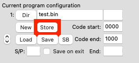
To get started:
Your configuration is ready!
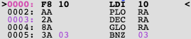
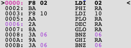
Write some code, for example a short counter going down from 10 to 0:
After writing this counter you realise you need to make the counter large, i.e. > FF, say 110.
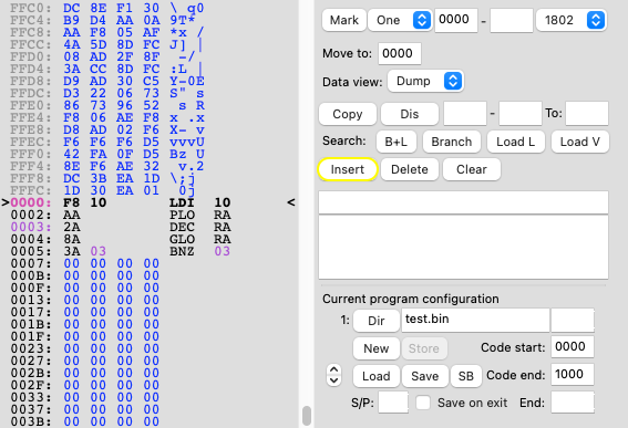
To do this go to address 0 and press 'insert' (highlighted in yellow) 3 times. When doing that also look at what happens to the BNZ 03 code. It will change on every 'insert'!
After the 3 inserts you have room to add: LDI 02 / PHI RA on address 0000 and 0002. Also add a check on RA.1 in the end and you get:
Delete works the same where it deletes the current instruction and changes all branches.
The reason to define program boundaries is so that the assembler 'knows' which parts of memory to check for branches. In the above address 0000 to 1000 will be checked.
Another nice feature of the insert/delete functions is that all short branches are converted to long branches if needed and if possible. Also long branches that can be converted to short branches will be changed.
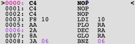
To have a look how this works write something like:
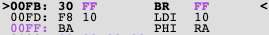
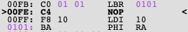
Do an insert on address 00FDh, the BR FF will change to a LBR 0101.
The direct assembler has inserted a NOP on 00FD but also added an extra byte to fit the LBR instead of the BR.
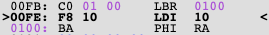
The same will happen with a 'delete' if no LBR is needed anymore it will be replaced by a BR. Note in the example above deleting the NOP on 00FE will not change to a BR. The LBR will still be to 0100 which means a BR doesn't fit so an extra delete for example on 00F5 would do the trick and change the LBR to a BR.
To save all 'debug' data, make sure to use the 'Save' button on the direct assembler tab. This will save the test.bin, test.debug and the configuration files. The '.debug' file includes info where branches and code are located. The configuration '.config' file includes info about the specified configuration. The whole configuration can be loaded back with a 'Load'. See section Program Configuration for more details.
If you start a COMX with the SB active, it is possible to load all SB FW configuration and debug data by pressing the 'SB' button. The SB configuration has a complex structure, consisting of 15 parts to handle the different ROM locations as well as different banks.